Professional Online Portfolio
443-852-4675
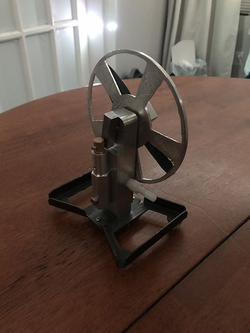
Flywheel Fabrication
In this project, I fabricated an air powered flywheel utlizing various machine shop tools including milling, casting, injection molding, plasma cutting, composite layup, and 4 axis CNC machining.
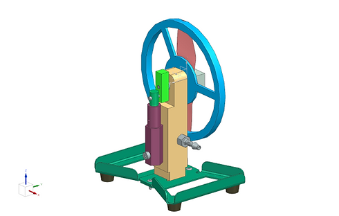
CAD Model
I first started off by creating a CAD assembly in Nx. The device works by blowing air into the nozzle (grey) which travels through holes in the backbone that drive a piston and crank shaft that ulimately spins the flywheel.

Kinimatic and Dynamic Simulation
To test if the structure would travel across a table top while spinning/vibrating, I performed a kinematic and dynamic motion analysis.
The coefficient of speed fluctuation is 0.022 or 2.2
Pressure = 62kPa
Radius = 4.7625mm
Area = 3.14*Radius^2
= 71.26mm^2
CS = (𝜔2 − 𝜔1)/𝜔1
= (-52.6 + 53.8)/-53.8
= 0.022
Force = Pressure*Area
= 4.418 N
IYY= 326.82998 kg·mm²
Mass = 0.6617 kg
Weight = 0.6617 * 9.81 = 6.49 N
Lateral Force = 6.49 * 0.1 = 0.649 N
Inertial Load = 0.723 N
It was determined the Lateral force generated by system imbalance at 500RPM is 0.723 N. Therefore, this force can cause the system to slide on its supports.
Flywheel Mold Base
The mold for the flywheel itself was created in Nx utilizing the CAM function by subtracting the flywheel from the base, creating tool path, post processing the tool path, and operation sheets.
The program data generated was used to create the mold base in a CNC machine.


Casting
The flywheel was casted with pewter. The edges of the mold were tapered to allow easier removal of the casted piece from the mold.
4 Axis CNC Machining
Utilizing Nx, I created the tools, tool paths, and G code for the CNC machine to run. The part created was the backbone of the flywheel assembly. It required spot drilling, drilling, milling, and tapping. The images below show the backbone (in yellow) fixed to a Haas CNC machine.


Composite Layup of Propeller
To create the propeller for the flywheel assembly, I layedup a multi-layer carbon fiber composite pre-preg on a mold.


Milling
I manually milled the crankshaft, piston, and cylinder. The tightest tolerance of position with my machining ability is +/- 0.002. I was able to control the movement of the mill in most cases by +/- 0.001, however there were some cases where the closest I could get to the true position was +/- 0.002.
Plasma Cutting
The base of the assembly was fabricated through plasma cutting sheet metal. The edges were then folded.


Injection Molding
The "feet" of the stand for the assembly was created through injection molding plastic
