Professional Online Portfolio
443-852-4675
Truss Structure Optimization
In this project, I designed a balsa wood structure within a given space envelope. I verified the design with a Nastran analysis to predict the ultimate load and failure mode. Then I built the structure with balsa wood, wood glue, and tested it to failure.

Goal
The objective is to design a truss structure for the maximum strength/weight ratio; this is defined as the failure load divided by the weight of the structure.
The structure will be placed in a rig such that the loading is similar to a force applied to the bearing surface. The load will be increased to a maximum of 250 lbf or until failure occurs.

Design Requirements
ONLY the materials supplied may be used = wood glue and balsa wood.
Size of individual balsa members cannot be changed (i.e. no splitting, no shaving, no sanding)
Laminations / overlapping joints are allowed and can be unlimited.
Stay within the space envelope (shown left) and touch the support only where allowed.
Do not paint, stain, or actively remove moisture from your structure.
Total analysis (by Nastran) weight ≤ 0.15 Lbf
Maximum allowable analysis load (buckling or stress) ≤ 250 Lbf.
The minimum load that the structure must handle is 10 lbf.
No curved sections.
Original Design
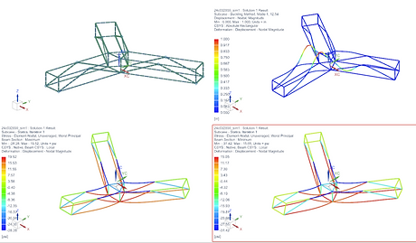
This was my initial design. Top left is the FEA model, top right is the first mode buckling analysis of the model, bottom right is the minimum stress of the model (highest compressive stress), and bottom left is the maximum stress (highest tensile stress).
This model has a maximum tensile stress of 19.5 psi, a maximum compressive stress of 31.4 psi, and a first buckling mode of 12.5. Its strength to weight ratio is 167. In these tests I used a test load of 1 lbF

Final Iteration
The initial reduction of the model involved eliminating members whose removal wouldn't sufficiently counterbalance the impact of weight reduction. The decision on which members to remove was based on iterative analyses using Finite Element Analysis (FEA) models, resulting in a notably lighter model. Subsequently, certain members were relocated or added to enhance the model's strength, determined through further iterations. The emphasis during this process was on increasing the lambda, as it served as the primary limiting factor in the design. Following this optimization, adjustments were made to the sizes of the members to further decrease their weight.
This model has a maximum tensile stress of 27.81 psi, a maximum compressive stress of 24.36 psi, and a first buckling mode of 39.17. Its strength to weight ratio is 590, and the failure weight is 39.17 lbF. This is the model that was ultimately built.

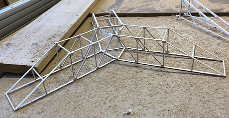
Construction
I estimated the structure would likely fail at its center, primarily due to buckling, with an anticipated failure at 39.17 lbs. While constructing the model, I consistently monitored the Nastran simulation plot for bending and element-nodal stress, confirming correct construction. To address practical issues, some beam members were slightly offset in location. I added reinforcement to nodes, absent in the Nastran model. Assuming a 1000 psi failure stress for Balsa wood, any lower value would shift design focus to material failure, necessitating measures to prevent beams exceeding material stress limits. A higher Modulus of Elasticity would diminish the importance of bending to strength-to-weight ratio, as more force would be required for buckling before material failure.
Test Results
After testing the structure to failure in real life, it was found that the structure was able to withstand 42.35 lbs and had a strength to weight ratio of 624. This increase was likely due to adding "scarfs" to prevent failure from occuring at the joints. As predicted, failure occured at the center of the structure in the middle of the members. This shows the FEA model was created properly and the physical model was accurately constructed to the FEA model.